- Poultry farm equipment layout connects building dimensions with feeding, drinking, ventilation, and service planning across commercial houses from 60–150 m long.
Automatic poultry equipment supports organized workflows, while carefully positioned components improve maintenance access and simplify future production upgrades without unnecessary reconstruction.
Poultry house equipment planning also coordinates airflow, water delivery, feed distribution, electrical routing, and environmental control through one integrated engineering approach.
Commercial layouts benefit from equipment geometry, practical service corridors, centralized automation, and expansion planning that protect productive floor area during daily operations.
- A coordinated poultry farm equipment solution converts separate machines into an engineered production system, creating measurable operational value for modern poultry producers.
Get professional poultry farm construction guidance, equipment selection solutions, and the latest price lists, whatsApp to +8618830120193, click to learn more:
Start With The House Before Choosing Equipment
A profitable poultry house begins with engineering rather than equipment purchasing.
Before selecting feeders, drinkers, fans, or controllers, define the building envelope, flock capacity, and service routes.
For example, commercial poultry farm equipment projects can use internal widths of 11–15 m and sidewall heights of 2.5–3.5 m, creating the foundation for an equipment-specific layout.
Automatic poultry equipment should be selected only after structural conditions, installation interfaces, and production requirements are confirmed.
Data is for reference only.Swipe horizontally to view full table.
A professional poultry equipment manufacturer can convert structural drawings into a coordinated installation plan before fabrication begins.
Build A Functional Equipment Grid
Treat the poultry house as an engineered grid rather than a room filled with machines.
Poultry house equipment should occupy defined functional zones, while service routes remain separated from routine bird-management paths.
A service route of approximately 1.0–1.5 m can accommodate inspection and equipment movement without unnecessarily interrupting production activities.
Automatic poultry equipment becomes easier to install when electrical points, water connections, and structural supports are established during the design stage.
A coordinated poultry farm equipment plan can also reserve 5–8% of usable space for service-related functions, preventing later modifications from disrupting production.
Data is for reference only.Swipe horizontally to view full table.
Optimize The Feeding System Around Equipment Geometry
Automatic poultry equipment should follow house geometry rather than being added after the floor plan is completed.
Poultry farm equipment selection must consider feeder dimensions, drive configuration, feed delivery routes, and structural mounting points.
Commercial systems can use pan diameters around 33–38 cm, while drive motors may fall within 0.75–2.0 kW, depending on configuration.
Automatic feeding equipment can connect storage, auger delivery, hopper distribution, and feeding pans into one continuous material-flow system.
Data is for reference only.Swipe horizontally to view full table.
The commercial advantage comes from treating automatic feeding equipment as part of a complete poultry house equipment package.
Integrated design reduces manual redistribution requirements and creates a repeatable material-handling process.
Position Drinking Lines For Efficient Water Distribution
Poultry house equipment planning should position drinking lines in relation to feeding routes rather than treating water equipment as an independent installation.
Closed nipple systems help reduce exposed water surfaces and support cleaner litter management when correctly installed.
For floor systems, water lines can be positioned approximately 0.6–0.9 m from feed lines, supporting efficient movement between feeding and drinking areas.
A poultry farm equipment package should include filtration, pressure regulation, water distribution, and flushing arrangements as interconnected components.
Data is for reference only.Swipe horizontally to view full table.
Automatic poultry equipment becomes more practical when water treatment and distribution are incorporated into the original engineering drawing.
Professional installation also allows water isolation and flushing points to remain accessible during routine operation.
Design Ventilation As An Airflow Path
Poultry farm equipment ventilation planning should begin at the incoming-air point and finish at the exhaust point.
Fans, air inlets, cooling pads, and environmental sensors must operate as one airflow system rather than as separate products.
Tunnel houses can use internal air velocities of approximately 2.5–3.5 m/s as engineering references, with fan selection calculated against building volume and climate conditions.
Poultry house equipment engineering should therefore evaluate airflow demand before finalizing fan quantity or placement.
Cooling-pad thickness can also be incorporated into the overall airflow calculation, with commercial evaporative systems commonly using 100–150 mm construction.
Data is for reference only.Swipe horizontally to view full table.
Professional poultry equipment suppliers can calculate airflow, inlet configuration, cooling requirements, and controller programming as a unified system.
The result is a ventilation layout based on engineering relationships rather than simply selecting the largest available fan.
Keep Maintenance Access In The Original Layout
Poultry house equipment requires service access throughout its operating life, not only during installation.
Motors, regulators, controllers, fans, and water components should remain reachable after production equipment is fully commissioned.
A dedicated maintenance route of 1.2–1.5 m can support inspection and equipment movement during scheduled servicing.
Automatic poultry equipment also benefits from accessible control assemblies, particularly where technicians need to inspect terminals or replace electrical components.
Approximately 45 cm of working clearance can be provided in front of frequently serviced control components.
Data is for reference only.Swipe horizontally to view full table.
A maintenance-oriented poultry farm equipment layout reduces the possibility of dismantling adjacent systems during routine servicing.
Such planning also creates a clearer relationship between equipment placement, technician access, and operational continuity.
Connect Automation With The Physical Layout
Automation becomes more valuable when poultry farm equipment is physically arranged around centralized control.
Feed motors, ventilation fans, water systems, lighting, and environmental sensors can operate through a structured control architecture.
A controller with 10–16 monitored zones can support centralized management for larger installations, depending on system configuration.
Automatic poultry equipment therefore becomes part of an integrated production network rather than a collection of standalone machines.
Data is for reference only.Swipe horizontally to view full table.
The commercial value becomes clearer when customers purchase a coordinated poultry house equipment system instead of isolated components.
Integrated controls can simplify commissioning, daily operation, troubleshooting, and future system expansion.
Use Six Questions To Test The Layout
A practical poultry farm equipment audit should be completed before manufacturing starts.
Access: Can technicians reach critical equipment without disrupting production?
Distribution: Can feed and water reach designated production areas through direct routes?
Airflow: Can ventilation components operate according to the intended airflow sequence?
Maintenance: Can worn components be removed without relocating neighboring systems?
Automation: Can major equipment groups communicate with the central control system?
Expansion: Can future equipment be connected without major structural reconstruction?
Reserve approximately 10–15% of selected equipment routes where future upgrades are expected.
Automatic poultry equipment projects benefit particularly from phased expansion because new components can follow established electrical, water, and mechanical interfaces.
Avoid The ''Machine-By-Machine'' Purchasing Method
Buying a feeder from one supplier, drinkers from another, fans from a third supplier, and controllers from a fourth can create compatibility problems.
Poultry house equipment requires coordinated electrical requirements, mounting dimensions, control signals, water connections, and installation interfaces.
Commercial systems may operate on 380–415 V, 50 Hz, three-phase power, depending on destination-market requirements and equipment configuration.
A poultry farm equipment manufacturer can instead prepare one engineering schedule covering feeding, drinking, ventilation, environmental control, lighting, and manure handling.
Automatic poultry equipment becomes easier to commission when control architecture and mechanical installation requirements are established under one project plan.
Plan For Future Capacity
Poultry farm equipment layouts should accommodate future production changes rather than serving only the initial production cycle.
Equipment positions can allow additional feeding lines, upgraded controllers, or improved ventilation components without rebuilding the house.
Feed storage can be configured around 10–12 t storage units where centralized feed management matches production requirements.
Poultry house equipment routes should also include planned electrical and water connection points before construction is completed.
Future expansion becomes more efficient when structural openings and service interfaces have already been incorporated into the original engineering documentation.
Choose An Equipment Manufacturer That Designs The Whole System
The most effective time to optimize poultry farm equipment layout is before construction and installation.
The recommended engineering sequence is:
House Drawing → Capacity Calculation → Equipment Layout → Manufacturing → Installation → Commissioning
Automatic poultry equipment can combine feeding, nipple drinking, ventilation, cooling, environmental control, lighting, and manure-management systems within one coordinated project.
Poultry house equipment engineering should align mechanical installation, electrical interfaces, water routing, control logic, and maintenance requirements before production begins.
A well-planned poultry farm equipment system turns each square meter into a functional part of the production process.
Frequently Asked Questions
Q1: What should be planned first in a poultry equipment layout?
Building dimensions and production capacity should be established before equipment selection.
Equipment positions can then be developed around airflow, feed distribution, water delivery, maintenance access, and control requirements.
A preliminary layout should also identify structural openings before equipment manufacturing begins.
Q2: How can poultry farm equipment improve space utilization?
Integrated equipment reduces unnecessary manual routes and allows feeding, drinking, ventilation, and environmental control to follow planned installation corridors.
A properly coordinated design can also preserve dedicated service areas without interfering with bird-management operations.
Q3: Why choose a complete poultry house equipment solution?
A complete system coordinates mechanical, electrical, water, ventilation, and control interfaces under one engineering plan.
Such coordination can simplify installation and commissioning while allowing future equipment additions through predefined connection points.
Taiyu (HK) Group - One Of China Most Famous Poultry Farm Equipment Manufacturer
Poultry farm equipment integrates automatic feeding, nipple drinking, ventilation, environmental control, and manure systems, with project layouts engineered for commercial houses up to 150 m long.
Global factory direct sales provide equipment manufacturing, technical documentation, component coordination, and project support through one commercial supply chain.
Poultry equipment projects cover feeding, drinking, ventilation, cooling, lighting, automation, and manure management according to regional electrical and structural specifications.
Turn-key engineering coordinates layout design, equipment production, installation guidance, commissioning, and project documentation from initial drawings through operational handover.
International project supply supports farm developers, distributors, contractors, and integrators seeking a single-source equipment package for scalable poultry production facilities.
Contact Us To Received Your Customized Poultry Farm Plan
Headquarters And Branchs
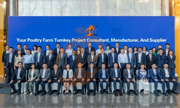
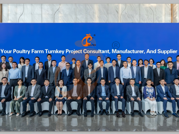
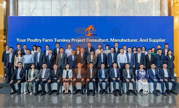
Hong Kong Headquarter Management Team
Hong Kong Headquarter Taiyu Industrial Group CO., LTD
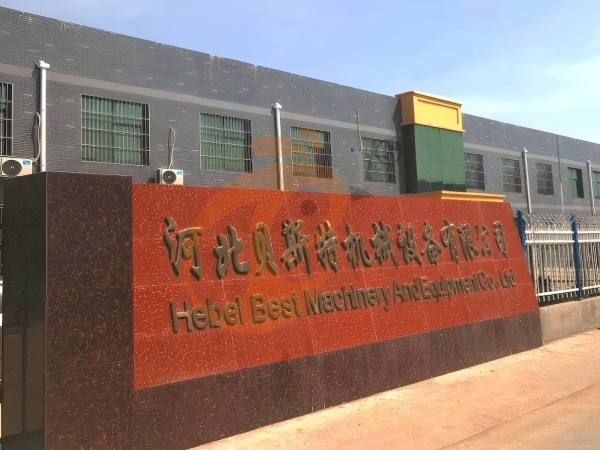
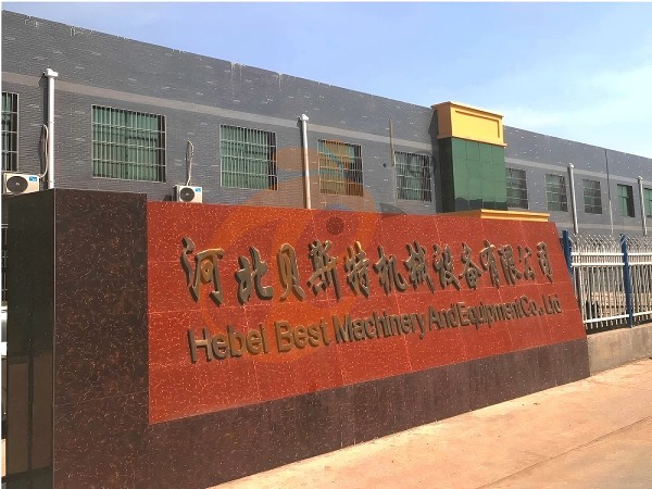
China Hebei Best Machinery And Equipment CO., LTD
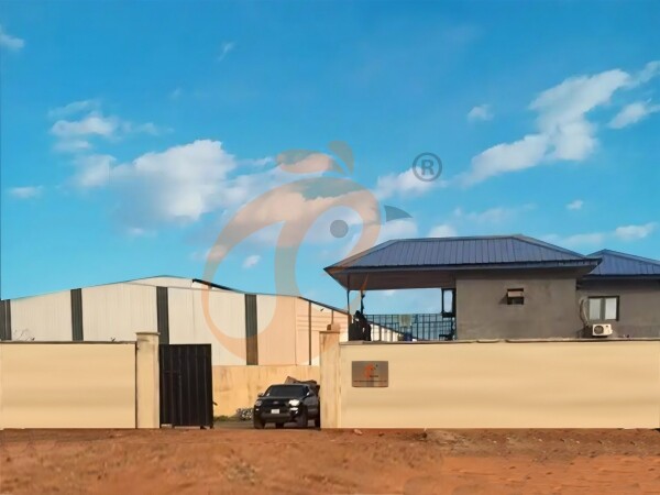
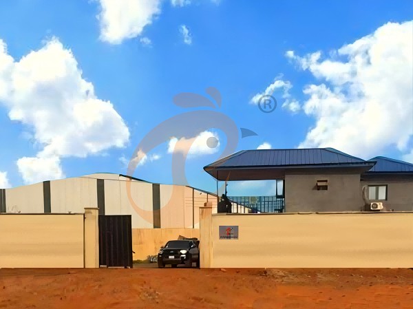
Nigeria Vanke Machinery And Equipment CO., LTD
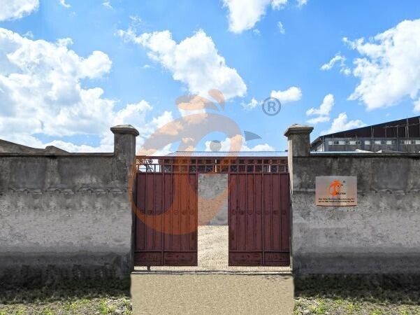
Tanzania Best Machinery And Equipment CO., LTD
Ethiopia Best Hebei Machinery Manufacturing PLC
Reception /24 WhatsApp NO. : +8618830120193
MESSAGE
Products recommended
 HK Headquarter Offers EU-standard Poultry Farm Solutions, Manufacture Poultry Farm Equipment1. Continuous communication with the EU and the US
2. China, Nigeria, Ethiopia, Tanzania branch companies and factories
3. The products’ quality is customized for local poultry farms
4. Poultry cage and poultry farm equipment stock for sale
5. 24 online reception Whatsapp NO. : +8618830120193,contact us to get full informationRead More China Branch Offer Poultry Farm Business Plan, Manufacture Poultry Farm Equipment1. Address: Flat/RM 2416, 24/F, Runxing Building, Youyi Nan Street, Shijiazhuang City, Hebei Province, China
2. Poultry cage and poultry farm equipment factory and stock for sale
3. Customized for local poultry farms
4. Quality and design are based on Euro
5. 24 online reception Whatsapp NO. : +8618830120193Read More Nigeria Branch Offer Poultry Farm Business Plan, Manufacture Poultry Farm Equipment1. Address: After Sinoma Office, 200 Meters Near Danco Filling Station, Lagos/Ibadan Expressway, Lagos State, Nigeria
2. Poultry cage and poultry farm equipment factory and stock for sale
3. Customized for Nigerian poultry farms
4. Quality and design are based on Euro
5. 24 online reception Whatsapp NO. : +8618830120193Read More Ethiopia Branch Offer Poultry Farm Business Plan, Manufacture Poultry Farm Equipment1. Address: Gelan Gura, Akaki-kaliti Sub City, Addis Ababa, Ethiopia
2. Poultry cage and poultry farm equipment stock for sale
3. Customized for Ethiopian poultry farms
4. Quality and design are based on Euro
5. 24 online reception Whatsapp NO. : +8618830120193, contact us to get price listRead More Tanzania Branch Offer Poultry Farm Business Plan, Manufacture Poultry Farm Equipment1. Address: No.8, Sova Road, Msufini, Mlandizi, Kibaha, Pwani, Tanzania
2. Poultry cage and poultry farm equipment factory and stock for sale
3. Customized for Tanzanian poultry farms
4. Quality and design are based on Euro
5. 24 online reception Whatsapp NO. : +8618830120193Read More Automatic H Type Layer Battery Cage System1. 30,000-100,000+ layers/house chooses it
2. Structure type stacked 3-16 tiers range
3. Stocking density up to 17 birds/cage
4. Service life 25 years
5. Reception /WhatsApp NO. : +8618830120193Read More Automatic A Type Layer Battery Cage System1. 10,000-30,000+ layers/house chooses it
2. Lifespan 25+ years
3. Labor requirement 1 worker per 10,000 birds
4. Reduce disease rates by 15%-20%.
5. Reception /WhatsApp NO. : +8618830120193Read More Semi Automatic A Type Layer Battery Cage System1. 1,00-10,000+ layers/house chooses it
2. Egg breakage rate≤ 0.5%
3. Mesh spacing 2.5×2.5 cm
4. Egg collection floor slope 7–8°
5. Reception /WhatsApp NO. : +8618830120193Read More